
DIY help for the Ampex 600 series
Ampex 600 series electronics
(I usually write "601" in the text as it is the most common)
Converting to a microphone preamp.
I have been promising a number of people that I would start sharing some of my modifications and schematics, since I am no longer taking orders for work. I have seen a variety of people do questionable modifications to 601s. I will be discussing some of these things in the text. I advise people to never buy a 601 which has been modified to use only 2 tubes per channel, ... if they want a 601 preamp that is. It may be a good, usable preamp but with only 2 tubes it is not a 601 preamp. A design which is loved by many.
Important Note: These schematics, charts, and perhaps other materials were never meant for publication. I use these charts and schematics when I am building preamps. The schematics are hand drawn and are not guaranteed to be free of errors. Nor are they complete. When I finally finish the last couple of projects, I will have time to make nice schematics, etc. for this page.
I am breaking
down this topic into several scenarios. I'll start with the simplest,
quickest, cheapest project design to get a good usable preamp.
Ampex 601 manual (EF86 schematic)
Simple repair / Recap
There are 3 tubes (not including the 5y3 rectifier) which are used when
a 600 or 601 electronics is used as a mic preamp: V101 (5879 or 6267,)
V102 (12ay7,) and V106 (12au7.) There are 5 capacitors in the audio
path which should be replaced: C102 - .1/400V, C104 - .047/400V, C106 -
.1/400V, C122 - .01/400V, and C123 - 4mf/150V. Film caps should be
used. The "rec cal" pot should be replaced with a pot which will accept
a knob. All the electrolytic filter and cathode caps should be replaced
also. It is easier but more expensive to replace the big can caps. Most
techs (including me) use individual caps under the chassis. This is not
a particularly easy thing to do in a neat way - plan ahead. The cables
hanging off can be removed. I really recommend replacing the can caps
for beginner DIY folks. One can also remove the tape / input switch and
use that spot to mount the pot for the "rec cal" pot. This is your
master gain.
Modifications
For those that want to take the 601 to another level, there are several
concerns: noise, features, sound quality including output iron, and
control of the gain stages. To embark on a project like this, one needs
to have soldering and DIY experience, as well as good tools. A
temperature controlled, high wattage (40W+) soldering iron is almost a
must. (You have to solder to the chassis and the ground buss.)
Noise: This is the most important concern for me. I want to be able to record a single instrument in silence without having to use a noise reduction plug-in. In the empty space between notes, I want empty space. No hum or hiss that is loud enough to matter; just a sense of air. Yes, this is subjective and is sometimes referred to as a "black background." The biggest source of objectionable noise in the 601 is induced hum. The power transformer of the 601 is simply too close to the audio transformers to achieve low noise. I never found a way to keep the 601 as a self contained unit and achieve low noise. That is why almost all of my units have remote power supplies with umbilical cord. And if you are making a dual mono preamp, the remote power supply (RemPS) is a must. Adding phantom power is much easier with the RemPS.
Another important noise source is the AC power for the tube heaters. I have tried quite a few different techniques for converting the heaters to DC. The one I found to work best is a floating heater circuit from the RemPS. Inside the preamp, I create the ground reference for the heaters with a pair of 100 Ohm resistors to ground. The 601 power transformer doesn't have a center tap style heater winding, so you have to use a full wave bridge rectifier. This is why I don't use the more common technique of grounding the center tap inside the RemPS. When I tried grounding the (-) side of the FWB rectifier inside the RemPS and only sending one wire to the preamp, it was noisier than the floating heater wiring I prefer. This should come as no surprise. Think about balanced and unbalanced lines and their relative noise issues. In this case it is more likely to be a situation where the ripple on the heater wire induces noise in the other wires of the umbilical, whereas the ripple from the 2 floating supply wires cancels out. The ripple on the heater supply is hard to filter because it is high amperage. The power supplies I build will have ripple of about .03VAC on the B+ supply (~270VDC) and .3VAC on the 6.3VDC.
Circuit Grounding: As was normal in the 50's, circuit ground is the chassis. There are ground connections all over the place. Some are soldered. Some are rivet connections. Star grounding and other improved grounding schemes came along soon after. For the more complex builds, I strip the 601 down to the bare chassis and rebuild from the ground up ... ... ...
Now is a good time to discuss some things. I am despised by many for what I do to 601s. If the 601 did not have the best mic preamp of all the Ampex recorders, almost all of them would be in the landfill, barring those few in museums and collections. Even Ampex collectors and experts say the 601 transport is useless for recording, but that doesn't stop them from raining down derision on me and others who salvage the preamps from the decks. There are hundreds of these preamps in studios all over the world. So the question often asked is "why?" "Why not just build a preamp from scratch and leave the 601 alone?" Two main reasons: 1) reusing and repurposing stuff instead of sending it to landfills and 2) show me where to buy a power transformer for 7 tubes, choke, nice lighted VU meter, chassis with tube sockets and alloy faceplate, 2 x ef86, 12ay7, 3 x 12au7, 6F5, 5Y3, nice mic transformer, output transformer, fancy XLR jack, fuse holder, power switch, knobs, etc., etc. for about $250.
... ... and when I do, I install a copper ground bus soldered to the chassis in one spot. This is one variety of star grounding.
Another source of low level noise is the mic/line mixing bus and pots. Changing this to a switched DI option for guitars is very popular. If you compare my schematic to the Ampex schematic, you will see that I remove the mixing bus, but I leave the resistors configured the same as if the line input pot was all the way off. This keeps the gain the same as designed by Ampex. This voltage divider can be replaced with another pot for even more control over the gain stages if desired. BTW - stepped attenuators are better than pots. The fact that the line input pot never goes to 0 Ohms causes low level noise in the mic circuit. As the temperature changes, the resistance fluctuates and adds noise to the mic signal. It took a lot of work to pin down the source of this low level noise which sounds similar to static-y noise from a noisy tube. Implementing the DI as I have done allows plenty of gain for guitars and is also usable with -10 or +4 line levels. It does change the phase of the DI to inverted. For heavy distortion and more transformer sound, use a matching transformer into the mic input. The DI is capable of some overdrive, but is meant for clean guitar and bass. The DI input pot can be 250k, 500k, 1M, ... whatever you want the input impedance to be for the DI. I have found the 250k to be fine for my taste.
Now I'm getting down to
things that will not really matter until you get the noise down with
the techniques above. When building the circuit I use low noise metal
film resistors. These are quieter than carbon resistors. Some people
say they prefer the sound of the carbon resistors. I don't.
I
use silver plated hookup wire and silver solder. I prefer ALPS rk
series pots (blue velvet) to carbon pots. Again, others like carbon.
The best choice is a stepped attenuator but they are pricey and large.
I like to use them for the mic level control.
The meter adds .3%THD to the output. I verified this by measurement but
I can't hear it. Some people might want to install a meter disconnect
switch. I don't usually do that.
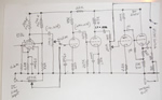 main circuit
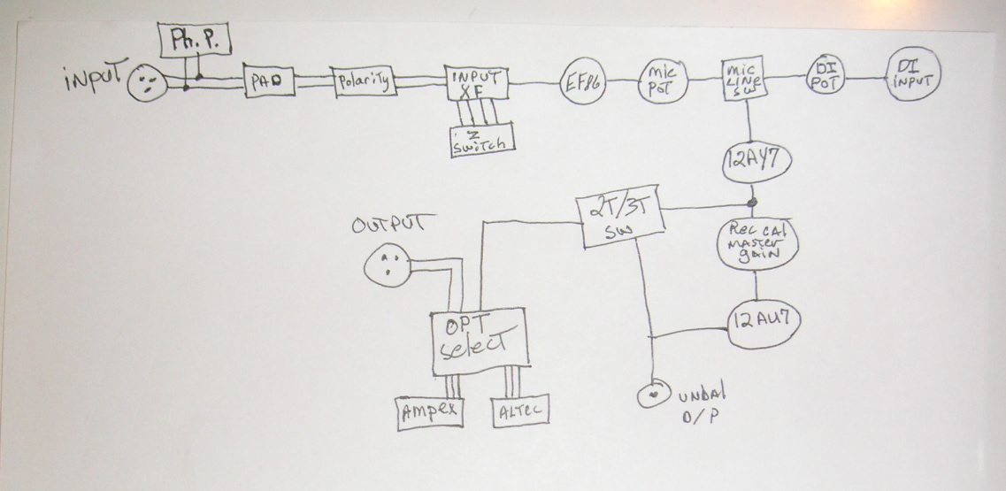 flow chart for fully loaded preamp - all options.
*** This page is under construction - more coming soon. ***
Do not remove tubes unless you are going to adjust the power supply circuits.
For use with a transport: The rest of the audio caps in the record amplifier and the playback amplifier should be replaced. The mica caps (domino) are fine and can be left. The plate resistors should be replaced with low noise metal film. The EQ networks and the whole unit will benefit from 1% metal film R's.
Changing the 5879 tube to 6267: When changing the tube socket wiring to use the 6267, be sure to cut away the ground wire connecting the socket's center pin to pins 2 & 6.
The right input transformer for the 601 is going to have either 17331 or 580022 on it (often w/prefix and/or suffix. I.E. 4580022-1D) Not 580200! Not 580116!
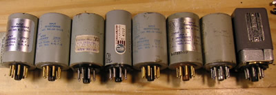
The one on the right is not from Ampex.
I often get questions from people who want to work on the 600 series recorders, both the electronics and the transport. I don't believe the transports are worth spending much money on. I used to repair the transports, but now I just advise people working on them as DIY projects.
Which tape to use
My
favorite tape for the 600 series is Quantegy / Ampex 632. You can also
use Scotch 111, Ampex 631, and others. 632 is not as common as 631, but
it is out there at good prices. The 600 series recorders won't erase or
bias tapes like 456.
The transport
The 600 and 601 transports are essentially identical. The heads, head
shield, mounting plate, and perhaps other parts from the 602 transports
are not interchangeable with the 600 and 601.
I strongly advise that only transports in very good condition be restored. If the heads are worn out, the pinch roller has a permanent dent (from being left in "play") or if any of the internal rubber parts or belts are bad; look for a better one. They are often free or very cheap. You should be able to buy several transports for the cost of having a pinch roller rubber or heads replaced. If a transport has been rigged in any way - run away. Unskilled people add shims, bend springs, and all manor of what the manual refers to as "tampering" when trying to get one of these working. The 600 series transports seem to inspire such tampering because their functioning is not very intuitive. "Tampering" will often render a transport unrepairable or needing replacement parts.
The manuals offer detail on assembly and disassembly, as well as calibration instructions. There is one section of the manual I have problems with. The functioning of the Play Clutch is not described well. I believe the instructions for adjusting this very important aspect are flawed. Perhaps a bad communication between the engineers and the technical writers was at fault. In the years when I was repairing these transports, not once did I ever get a 600 series in my shop with a working play clutch. I suspect that most repair techs that worked on these, misunderstood the design and went by the manual. If this is not carefully set, the machine will default into an alternate operating mode which eventually wears out the clutch parts and increases wow and flutter.
(Old Play Clutch video) - This video shows the proper operation of the play clutch, the holdback springs, and the tire brake. Please download the file to play the video.
In the first part of the video, you will see the play clutch which includes the round rubber belt, the alloy pulley, the plastic disc, and the felt covered alloy plate. As you can see, the plastic disc is supposed to slip against the felt. It is very common for the drive belt to slip instead of the felt. If you follow the instructions in the manual for setting this you will almost certainly end up with this alternate operating mode. As you can see in the video, this unit operated like that long enough to wear the belt flat. I have seen units where the plastic clutch was worn completely through (cut into two pieces.) As the camera pans down you can see where the belt is running on the plastic disc. You can also see a darkened band to the right of where the belt is now. That is where it was when I received the unit. It is where the manual would have you set it with the feeler gauge technique. This is where I believe the manual is wrong, or at least confusing.
The belt must not slip against the plastic disc. In the alternate operating mode, the unit will function but the wow and flutter goes up. I find myself wondering whether they came from the factory that way. They can run for years in this alternate mode before the clutch parts wear out, but the clutch is not controlling the pull tension. The slipping belt is! This makes the wow vary unpredictably.
As the camera pulls back and moves to the other side, you will see the wheel, tire, alloy plate w/felt, and brake of the holdback tension system. Once again, it is supposed to slip on the felt, but often does not. As the rubber of the tire ages and hardens, the tire will start slipping on the brake instead. Often they will both be slipping. This "stick-slip" action causes severe variation in the holdback tension. This same system handles the FF and RW clutch action. With a heavy reel of tape on the machine, the wheel will slip against the felt as it comes up to speed. The little question mark shaped springs with felt on them provide light holdback braking for the FF and RW functions. They only contribute a small amount to the holdback tension. People often try to make them do things for which they were not designed.
Sanding the rubber:
The right way to repair the aged rubber parts is to replace them with
new ones or have them "recapped" (new rubber applied.) This is usually
impossible or WAY too expensive for these machines, so sanding the hard
rubber off is the next best option. There is plenty of "take-up" in the
design to allow for removing a small amount from the rubber parts.
Here's how I do it:
1) Remove the wheels/tires being careful to observe the locations of the fiber washers.
2) Mount a 1/4" drill bit in a variable speed drill.
3) Mount the wheel on the drill bit.
4) Use 320 to 600 grit wet/dry sandpaper and do the sanding wet. You can wet and rinse the paper as you sand.
5) Use a flat sanding block and run the drill at a low to moderate
speed. Keep the rubber cool by rinsing as you sand. You will know you
are done when you dry the tire and can see an even matte finish all the
way around. No shiny spots.
6) The pinch roller can be cleaned in place. Use a flat block with the
sandpaper (a paint stirring stick works.) Be careful not to use much
water. Just rinse the paper a few times. Put the deck in play and sand
the pinch roller. Do NOT sand the capstan. Control any water. Don't let
water get into the capstan bearings. The deck needs to be vertical,
BTW. Clean the roller and capstan when finished.
The brakes should be cleaned too. They are the little metal wheels with the serrated edges. Clean out the grooves and clean the surface with solvent (like goof-off) and a Q-tip.
Felt: The felt parts can be cleaned with soap and water if they are packed with oily residue. If the felt was severly compressed, I used to pick at it to loosen it some with a stiff wire brush. Replacing the felt isn't recommended. If it is that bad, the rest of the transport is probably worn out too.
This chart shows the typical frequency response curves of a 9er-ized 601. Please notice that I didn't use the common marketing trick of setting the dB scale to make this look flat. The vertical divisions are only 4 dB, so you can actually see the variations. I've pushed the frequency response of these preamps down to about 10 Hz in an attempt to minimize phase distortions in the audible low end. I'm very happy with the bass sound I get using this preamp.
