This is an upgraded single channel 601
with add'l Altec 15095 output
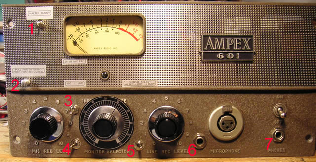
The main controls are the Mic Rec level, the Line Rec level, and the master gain which is the one in the middle with the black dial. The master gain control only functions with the main output. The Altec output is taken from an earlier point in the circuit for the cleanest, shortest signal path possible. It's the extra circuitry in the main output that provides overdrive, more tube coloration and extra gain, but its sound is not as transparent as the Altec output. The Altec output is for when you want the clearest sound.
Features, pictures, sample sound files, and tech notes below: 1) The meter switch - selects the Main or Altec output for the meter. Center position is off. This is useful when driving the unit hard and pegging the meter. Turn the meter off to protect it under extreme circumstances. The meter also adds .3% THD to the output it is monitoring. After setting levels, the meter may be turned off if desired. 2) Impedance switch - Pull for 30 - 50 Ohm microphones; push for 150 - 250 Ohm microphones. 3) 20 dB microphone pad - Up = on. For use with loud sources and hot microphones. 4) Mic / Line switch - Left = XLR Mic input; Right = unbal 1/4" TS line input (See #6) 5) Output switch - Left = Altec output; Center = both outputs; Right = Main output (think of A-B-C: Altec, Both, Cathode follower) When using both outputs, the termination on the Altec output should be turned off for best results. 6) 1/4" unbal Hi-Z line input - suitable for line level or instrument level sources. 7) This "phones" output is interesting because it has a little different sound than the main output. The main output goes through the output transformer and the phones output does not. It is Hi impedance and suitable for feeding a guitar amp or mixer. The phones output is part of the main output circuit. If the main output is turned off by the output select switch, there will be no output at the phones jack either. Sample Recordings Voice test file (192 kbps mp3) Music test file (192 kbps mp3) . Music test file #2 (192 kbps mp3) All tracks recorded with this preamp, most with a Studio Projects C-1. The preamp was fed directly into my AD converter and recorded in my DAW. No processing at all on the individual tracks (including no EQ.) The only processing applied: No EQ, no noise reduction, no games. *There are a couple exceptions where I am using the distortion effects on the cathode follower only and it is panned center.
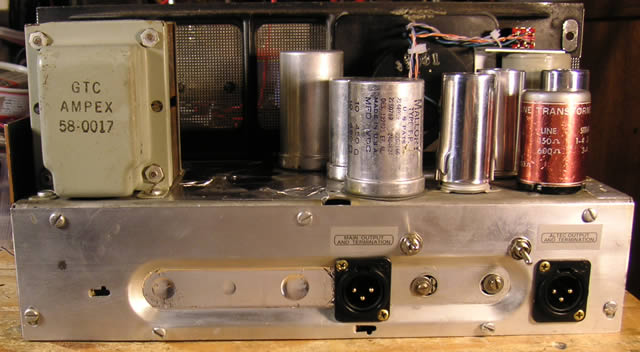
The output termination switches are used when feeding the input of a modern device. The main output was designed for a 600 Ohm load, so unless you are plugging into a vintage device with a 600 Ohm input, the termination switch should remain on. The Altec is also designed for a 600 Ohm load but in this circuit, I prefer the sound of the Altec 15095 when unterminated. If the Altec termination is turned on when you are using both outputs at the same time, it will load the circuit down. I recommend turning the termination off on the Altec output when using both outputs simultaneously. I usually leave it off as default.
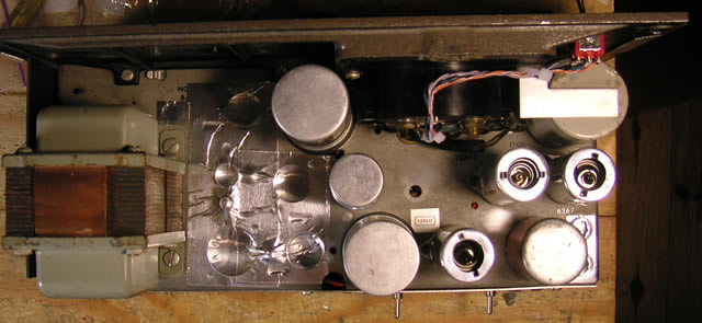
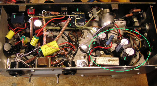
For the techies, here are some of the electronic features: In the circle is the power supply section. It has been condensed and moved as far from the audio circuits as was practical. The original AC tube heater supply has been converted to DC, and the tube rectifier has been replaced with Silicon diodes, mostly to lower the heat produced by the unit. All the electrolytic capacitors are 105 degree Nichicon. 1) Alps "Blue Velvet" pots for the mic and line input level controls 2) Auricaps (yellow cylinders) are used in the signal path with one exception: there is a polystyrene cap replacing the original ceramic disc in the cathode follower section. 3) Copper braided shield conduits for the silver hookup wire. The original used unshielded wire for these spots. I also use OHNO mono-crystal copper wire for the very low signal level wiring of the input transformer and impedance switch. I am not a big believer in these audiophile wire technologies. I can't say for sure that they make a difference in sound. I got good deals on some Belden silver/teflon hookup wire and the OHNO copper wire so I am using them. It only adds a couple dollars to the cost of the build so why not. I avoid hookup wire anyway and prefer direct connection of components, so not much is required. 4) This is the rectifier section for the tube heaters. 5) These are the big caps and diodes of the high voltage section (B+) I decided to add small "bypass" caps to the big filter caps, even though these caps (low ESR) aren't supposed to need them. I did this after testing revealed more high frequency hiss than I was happy with (under demanding circumstances - I can be very picky.) This remedied the problems and made me happy :-) In testing I got 87 dB below full scale as a noise floor and I didn't even try to tweak it for a maximum "rating." Click the links for sample recordings and demonstration of features (voice.) I don't provide specs for several reasons: |