Ampex 601 Dual Mono Preamp
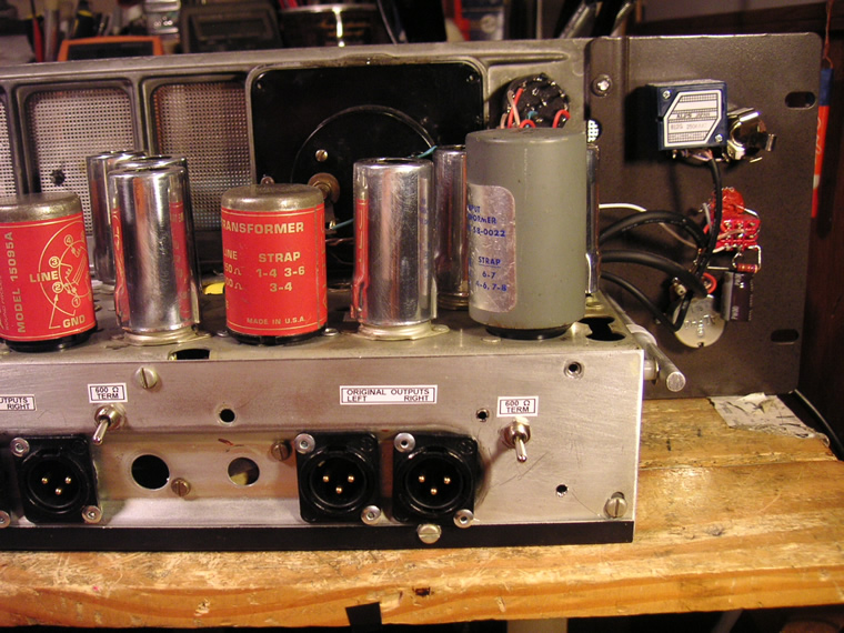
Note: This is an older design with the original Ampex output transformer plus an Altec 15095.
(see The 2T/3T option)
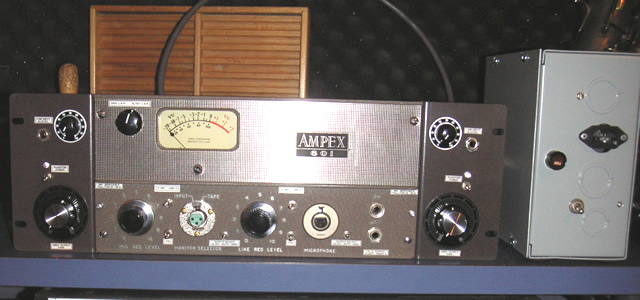
The unit below has two Ampex 601 channels, with their full original circuit paths, plus the addition of an Altec 15095 tapped off before the output section (the 12AU7 tube and the original output transformer.) This is a dual mono unit which features Auricaps, stepped attenuators, ALPS Blue Velvet line input pots, remote power supply with DC filament power, 48V phantom power, vintage Mullard EF86 tubes, 20 dB mic pad, and more to be discussed later.
Each channel has three separate outputs, all of which CAN be used simultaneously.
Original output #1 would be the original balanced output of the 601. This incorporates the "Rec Cal" pot (Orig Output Gain,) the 4th gain stage and the cathode follower (12AU7 tube,) and the small 601 output transformer.
Original output #2 is the unbalanced, Hi-Z "Phones" output of the 601. This is the same as #1 except that the signal does not go through the output transformer and is high impedance. This will feed a modern mixer, AD converter, or similar device well and it has a slightly different sound than the 600 Ohm Original balanced output.
Altec 15095 balanced output: This output only utilizes the EF86 and 12AY7 tubes, plus the Altec output transformer. This is my output of choice for most purposes. It is less colored than the full original circuit path, but it does not have the overdrive capability either. For driving the tubes harder even to the point of saturation, the original outputs are the ones to use. You turn down the Gain control and turn up the input level to overdrive the unit.
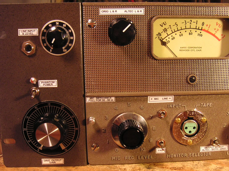
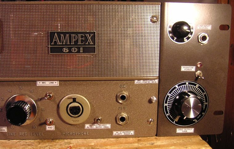
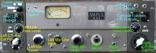
Above you see all the controls for the left side, plus the meter select switch:
The meter select switch selects which output will be shown on the meter.
Tip: The meter adds a small amount of distortion (~.3 THD.) I recommend turning the meter to an unused output after using it to set levels. The distortion is very hard to hear, but why not avoid it, if it's that easy?
Line input: For instrument level (elec guitar) 80 - 100% works well. For line levels, 25 - 40% is typical. I have found this to yield a great sound when you warm up the guitar just a little with the preamp, then run it through an amp simulator plug-in. I was amazed by how much better it made the simulator sound. It gets an excellent crunch with just the preamp, too.
Phantom power: 48V Phantom power. Please do not plug or unplug mics with the phantom power turned on.
Original Output Gain: This is the "Rec cal" pot which serves as a gain control for the original outputs. One can use this control to attenuate the output of the preamp section which allows one to overdrive the preamp. It can also be used to dial-in less severe attenuation to explore the variety of sounds available as the tubes are driven to various levels.
Please note that the Gain control only affects the Original outputs. For the cleanest most transparent sound, I recommend the Altec outputs.
Mic input impedance: Pull the knob for 30 - 50 Ohm mics (usually ribbons) and leave it in for 150 - 250 Ohm mics (most condensers and dynamics.)
Pad: This mic pad (20dB) is intended for use with 150 - 250 Ohm mics, not low Z ribbons.
Output select Altec - Both - Original: Much of the time this switch can be left in the "Both" position. For times when you don't want to use both sets of outputs (Altec + Orig,) I recommend setting the output switch to only the output actually in use; especially for critical tracks like vocals.
Tips:
*Typical Mic input levels with hot mics is about 1 - 4.
*Guitars can go into the line input or into the mic input through a matching transformer or DI box for more gain.
*Using both outputs from one channel (I.E. left Altec O/P + left Orig O/P) as a stereo pair is an interesting application. This gives one a pair of "stereo" outputs from 2 microphones or 2 line sources. After recording, one can use either side or both in a variety of ways.
*I recommend leaving the output termination OFF for the Altec 15095 outputs. This is almost a necessity if you want to use the Orig outputs at the same time. The termination will affect the loading of the circuit and its sound. 600 Ohm output termination is recommended when feeding modern gear without input transformers. It should be off when feeding a 600 Ohm transformer balanced input like found on most vintage gear. Having said that, I like the sound of the Altec outputs unterminated and I find the Orig outputs to be almost unaffected by the termination. Termination affects frequency response and is intended to provide the right impedance environment for the flattest performance. It's not very important when the unit is used as a mic preamp, but could be more important when running whole mixes through the preamp.
For affecting stereo mixes and other tracks:
Here is an example with a CD player to get you started, then experiment:
1) Plug the CD player into the line-in inputs on the front.
2) Set the mic/line switches to the right.
3)
Turn the line-in level controls all the way down.
4) Set the gain controls to about 4 if you are using the Orig outputs .
5) Start the CD player, then gently turn up the line-in levels until you get peaks around -5 VU. Use care and get the levels the same on the left and right. For critical work like working on a master, one should use a mono test signal to set the 2 line-in level controls so they are exactly the same.
6) Now use the input level controls and the gain controls to adjust how much warmth you want to add to the sound. I find that with peaks at or below 0 VU, there is just a nice sheen on the highs and silky power in the lows. As the peaks go into the red you will start to hear distortion FX - salt to taste ;) Use the gain control to prevent clipping of whatever you are plugging the preamp into, if necessary.
Below we see the controls for the right channel, plus the High Z unbalanced outputs for both channels.
For instruments: Now here's an application that can get a little crazy. If you use a matching transformer (or DI) into the mic input for your guitar or bass, then feed the unbal high Z output of that channel into the line input of the other channel, you can get the following signal path:
Guitar --> matching XF/DI --> Ampex input XF --> EF86 gain stage--> mic level control --> 12AY7 gain stage #1 --> 12AY7 gain stage #2 --> Gain control --> 12AU7 gain stage --> 12AU7 cathode follower --> patch cord to line input of Ch2 --> 12AY7 gain stage #1 --> 12AY7 gain stage #2 --> Gain control #2 -->12AU7 gain stage --> 12AU7 cathode follower --> orig output XF.
All these tube stages with all these level controls should bring a smile to even the most extreme bottlehead.
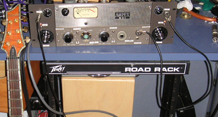
In the pic below, I was going in through the line input, not the mic input.
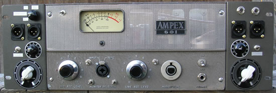
AMPEX 601 Dual Mono Altec Rack
This design offers 2 matched preamp channels. Each has the full original circuit path of the 601 and the addition of an Altec 15095 output transformer tapped off after the microphone preamp section of the 601. This customer wanted all I/O on the front:
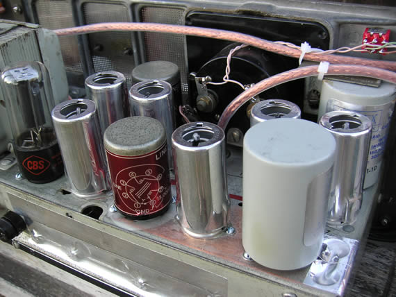
The tape electronics section has been converted to a second mic/line preamp channel. Old carbon composition resistors have been replaced with Dale/Vishay 1% metal film resistors on both channels so they will match for use as a stereo unit. This has been completely recapped with Nichicon PW series electrolytics, Auricaps, polystyrene replacements for ceramic discs, and a few orange drops.
Here's a sample recording of 2 classical guitars recorded through this preamp. The only processing applied is a little reverb and a limiter on the main buss. No EQ, noise reduction or other trickery.
In the past, I have tried to use some of the old caps to try to preserve more of the "vintage sound." Even desirable caps reported to last (Budroc, Bumble bees, and ceramic caps) are failing these days and finding caps originally spec'd at 5% tolerance which are 100% or more out of spec has lead me to start replacing all the important components with high quality modern components. For those that are looking for that "vintage sound," please consider: when these units were fairly new, these components would not have been so out of spec. What you get with a deteriorated vintage unit is not the same performance that was achieved when they were new. To me, what is most important about the "vintage sound" comes from the tubes, the tube circuitry, and the transformers (The Iron!) Supporting those components with high quality caps and resistors provides excellent performance.
Features:
Note: This is an older design with the original Ampex output transformer plus an Altec 15095.
(see The 2T/3T option)
All The important controls and I/O have been brought to the front for rack mounting. The hum balance pot and the fuse are the only things not available from the front.
1) Metering - One of the things I really dislike is when companies try to hide the drawbacks to their product through misdirection and misleading ads. I will tell you straight out about the things that are not ideal about a design. In this design, the metering isn't great. With 4 outputs (L/R Altec and L/R CF) and only one meter, one has to accept that the metering is limited. I felt it was very important to be able to check levels for all the outputs, so I designed the metering options to allow for this. There is a rotary switch (Output Meter Select) which selects the output to be metered. Then one can flip the L/R meter select switch between L and R. According to specs, the meter adds up to .3% THD. Some may wish to turn off the meter after setting levels.
2) Mic / Line switches - Individual switches means that one may use the mic input on one channel and the line input on the other. Flip the switches up for Mic and down for Line. (the left switch is for the left channel, the right switch is for the right.) To help remember: When the switches are in the MIC position (up) they are more out of the way of the XLR inputs.
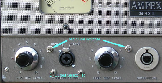
3) Monitor selector switches (Output Select) - These switches select the output for each channel. In the left position, the Altec output is active. In the right position, the cathode follower output is active. There is also a middle position which makes both outputs active. So we have (A)ltec, (B)oth and (C)athode follower; from left to right. I chose to try to make the design logical enough so I would not have to slap labels all over it.
I don't recommend using the BOTH position casually. The individual outputs perform better when only one output is selected. The BOTH position is nice for blending and/or panning the different colors of the different outputs - like plugging in a guitar and using the clean output of the 15095 panned a bit left and a crunchy tone from the C/F panned a bit right.
There are some strange things that can happen with certain combinations of these switches, what the outputs are feeding, and the termination switches. Nothing harmful, but you will have some loss of gain from the extra loading of the circuits. Rule of thumb: When using both outputs, turn off the termination for the Altec outputs for best results. In fact, I prefer the sound of the Altecs when unterminated in most situations.
4) Line inputs - (unbal. 1/4" TS 250k impedance) The new channel uses a Neutrik combo jack for both the XLR and line inputs. These inputs are suitable for electric guitars as well as line level outputs from a CD player for example. These preamps work beautifully as the front end for a listening system. I listen to music played on a CD player and run into the line inputs, with the outputs of the preamp feeding my power amps and speakers - nothing else in the signal chain. The sound is very good.
5) L/R Unbal C/F Outputs - These are good for use as a Hi-Z, unbalanced output to feed a mixer, sound card, or similar device. This is an important feature for those that like different colors because these outputs do not go through an output transformer and they have a slightly different sound compared to the 600 Ohm balanced outputs.
6) Termination switches - These are the switches located next to the line level input controls. Up is 600 Ohm termination on, down is off. These switches allow one to turn off the termination which is usually desired when feeding modern gear with a vintage 600 Ohm output. When feeding modern gear, the termination allows for proper frequency response from the circuit. However, there may be times when a different flavor is desired or even more gain, so I have found that there are no rules when it comes to whether you use the termination or not. (well, ... actually one strong suggestion: When using both sets of outputs at the same time, I recommend turning off the termination on the Altec outputs.)
7) Cathode Follower "Rec Cal Pot" - I have replaced the original screwdriver adjusted "rec cal pots" with these nice new pots, knobs and faceplates. These controls serve as master level controls for the cathode follower outputs. One uses these to control the amount of "tubeyness," "color," or distortion - take your pick. If one turns these controls down and turns up the input levels, more color is the result. Everything from a filthy, nasty grunge to a very clear sound is possible. These controls only work with the cathode follower outputs. The Altec outputs provide the cleanest sound and simplest signal path, but don't have the overdrive capability of the cathode follower sections.
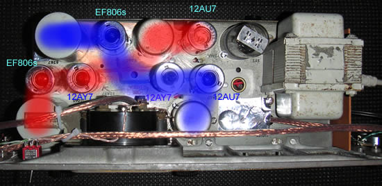
--------------------------------------------------------------------------------------
The following shows the components for the 2 channels. This will help when tube swapping. The red shaded components are the left channel and the blue ones are the right. (sorry for breaking convention here. Red should have been right.) There are painted stripes on the chassis to indicate the channel paths.